Getting Started with ESP8266 Programming – Arduino
ESP8266 WiFi Module
The ESP8266 WiFi Module is a self contained SOC with integrated TCP/IP protocol stack that can give any microcontroller access to your WiFi network. The ESP8266 is capable of either hosting an application or offloading all Wi-Fi networking functions from another application processor. The applications of ESP8266 are Smart power plugs,Home automation ,Wi-Fi location-aware devices,Industrial wireless control,Security ID tags.
Features of ESP8266
- 802.11 b/g/n protocol
- Wi-Fi Direct (P2P), soft-AP
- Integrated TCP/IP protocol stack
- Integrated TR switch, balun, LNA, power amplifier and matching network
- Integrated PLL, regulators, and power management units
- +19.5dBm output power in 802.11b mode
- Integrated temperature sensor
- Supports antenna diversity
- Power down leakage current of < 10uA
- Integrated low power 32-bit CPU could be used as application processor
- Wake up and transmit packets in < 2ms
- Standby power consumption of < 1.0mW (DTIM3)
Prerequisite for programming
Installing ESP8266 Board in Arduino IDE
ESP8266 community created an add-on for the Arduino IDE. So before starting with ESP8266 first install Arduino IDE.
Installing ESP8266 to Arduino IDE
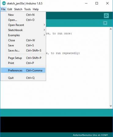
1) Open Arduino IDE, Open preferences window from Arduino IDE. Go to File -> Preferences.
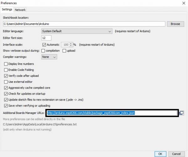
2) Enter the URL “http://arduino.esp8266.com/stable/package_esp8266com_index.json” into Additional Board Manager URLs field and click the “OK” button
If you already have a URL in there, and want to keep it, you can separate multiple URLs by placing a comma between them.
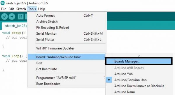
3) Open Boards Manager. Go to Tools -> Board -> Boards Manager
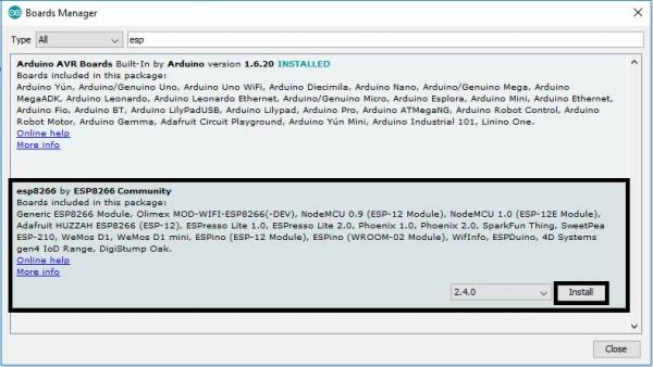
4) Search ESP8266 board menu and install “esp8266 platform”
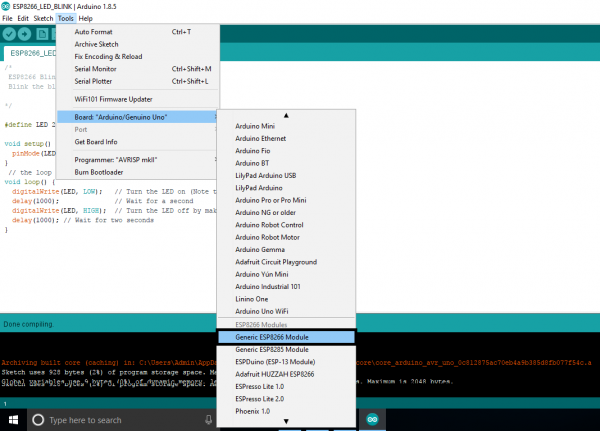
5) Choose your ESP8266 board from Tools > Board > Generic ESP8266 Module
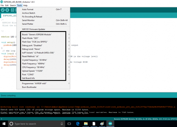
6) Selected Board details with Port selection
7) Re-open your Arduino IDE
Bootloader Modes
The bootloader can go into a number of modes depending on the state of GPIO’s 0, 2 and 15. The two useful modes are the UART download mode (for flashing new firmware) and the flash startup mode (which boots from flash).
| GPIO 0 | GPIO 2 | GPIO 15 | |
| UART Download Mode (Programming) | 0 | 1 | 0 |
| Flash Startup (Normal) | 1 | 1 | 0 |
| SD-Card Boot | 0 | 0 | 1 |
For ESP witty you have to hold the Flash button only while programming, No need to reset. Few boards may not require any user actions.
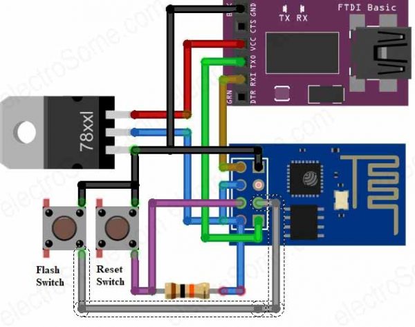
Circuit Diagram
Flashing Steps
The module can enter a number of bootloader modes depending on GPIO pin states. To flash NodeMCU (or any other firmware) you’ll need to connect the following pins:
- GPIO 0: LOW
- GPIO 2: HIGH
- GPIO 15: LOW
Apply 3.3V and GND and use a 3.3V UART to connect the device to a computer.
Follow the below steps to put device in serial programming mode before clicking on upload icon
To upload program to ESP on some boards you need to hold flash button while uploading and some boards require reset with holding of flash button.
- Press and hold RST button.
- Press and HOLD FLASH button while RST is in pressed condition.
- Release RST while FLASH is in pressed condition or on some boards hold it during program upload.
- Release FLASH after releasing RST
LED Blinking
Program
Edit this below code in Arduino IDE.
/*
ESP8266 Blink
Blink the blue LED on the ESP8266 module
*/

#define LED 2 //Define blinking LED pin

void setup() {
  pinMode(LED, OUTPUT); // Initialize the LED pin as an output
}
// the loop function runs over and over again forever
void loop() {
  digitalWrite(LED, LOW); // Turn the LED on (Note that LOW is the voltage level)
  delay(1000); // Wait for a second
  digitalWrite(LED, HIGH); // Turn the LED off by making the voltage HIGH
  delay(1000); // Wait for two seconds
}
2) Save the above code.
3) Compile the above code by clicking on Compile icon.

Uploading Code
Click on Upload Icon

Below error may occurs due to incorrect COM port or flash button is not pressed properly (i.e. device is not in serial programming mode) or may be no connection in USB to serial converter and ESP Serial.

Below result we will get after successful uploading of code into ESP8266

Hardware Result: Inbuilt Blue LED of ESP8266 starts blinking after the successful uploading of the above code to ESP8266 WiFi Module.
Note: ESP-12 and ESP-01 has blue color on board LED. Which is connected in reverse i.e. Anode(+ve) of the LED is connected to VCC and cathode (-ve) is connected to ESP-12 GPIO2. It means that LED becomes on when we output LOW and off when we output HIGH. This pin is also Tx, you cannot use serial when using this pin as LED.
Comments