LED Control by ESP8266 as Web Server – IoT
Here we are programing ESP8266 as a web server, the chip enables WiFi connectivity and can be turned into a small functioning web server. We will connect ESP8266 to our local wifi network and we can control the LED through this local network. If you need to control it through internet you can use DDNS and port forwarding.
Components Required
- ESP8266
- Resistor 470Ω
- LED
- USB cable
- Connecting wires
Hardware
Circuit Diagram
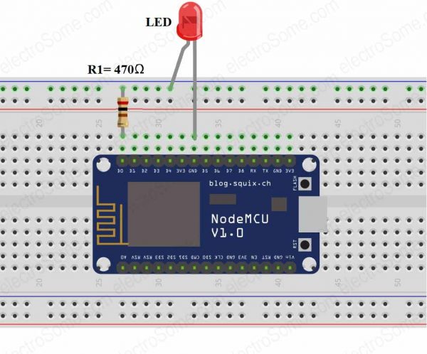
Connections:
- Connect LED positive terminal to D0 pin of ESP8266
- Connect LED negative terminal to one end of Resistor 470Ω
- Connect another end of Resistor 470Ω to GND terminal of ESP8266.
Software
#include <ESP8266WiFi.h>
const char* ssid = "WiFi Name (SSID)";
const char* password = "WiFi Password";
int LED = 16; // led connected to D0
WiFiServer server(80);
void setup()
{
Serial.begin(115200);
pinMode(LED, OUTPUT);
digitalWrite(LED, LOW);
Serial.print("Connecting to the Newtork");
WiFi.begin(ssid, password);
while (WiFi.status() != WL_CONNECTED)
{
delay(500);
Serial.print(".");
}
Serial.println("WiFi connected");
server.begin(); // Starts the Server
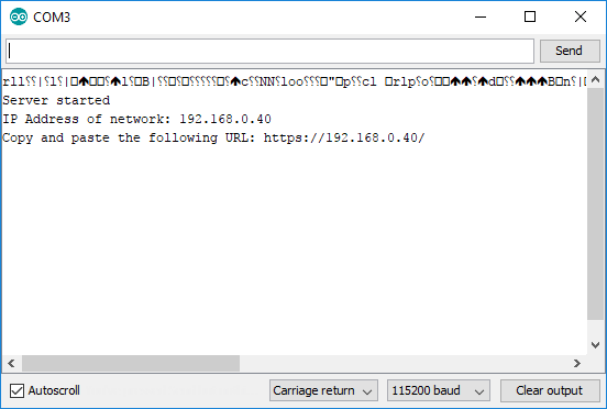
Serial.println("Server started");
Serial.print("IP Address of network: "); // Prints IP address on Serial Monitor
Serial.println(WiFi.localIP());
Serial.print("Copy and paste the following URL: https://");
Serial.print(WiFi.localIP());
Serial.println("/");
}
void loop()
{
WiFiClient client = server.available();
if (!client)
{
return;
}
Serial.println("Waiting for new client");
while(!client.available())
{
delay(1);
}
String request = client.readStringUntil('\r');
Serial.println(request);
client.flush();
int value = LOW;
if(request.indexOf("/LED=ON") != -1)
{
digitalWrite(LED, HIGH); // Turn ON LED
value = HIGH;
}
if(request.indexOf("/LED=OFF") != -1)
{
digitalWrite(LED, LOW); // Turn OFF LED
value = LOW;
}
/*------------------HTML Page Creation---------------------*/
client.println("HTTP/1.1 200 OK"); // standalone web server with an ESP8266
client.println("Content-Type: text/html");
client.println("");
client.println("<!DOCTYPE HTML>");
client.println("<html>");
client.print("LED: ");
if(value == HIGH)
{
client.print("ON");
}
else
{
client.print("OFF");
}
client.println("<br><br>");
client.println("<a href=\"/LED=ON\"\"><button>ON</button></a>");
client.println("<a href=\"/LED=OFF\"\"><button>OFF</button></a><br />");
client.println("</html>");
delay(1);
Serial.println("Client disonnected");
Serial.println("");
}
Code Explanation
We are including ESP8266 WiFi library which provides ESP8266 specific WiFi routines and we are calling to connect to network.
#include <ESP8266WiFi.h>
Get and enter the “ssid” and “password” i.e., your WiFi name and password.
const char* ssid = "WiFi Name (SSID)";
const char* password = "WiFi Password";
Set D0 as output pin. Start the server, initialize the serial communication with baud-rate 115200.
int LED = 16;
WiFiServer server(80);

void setup()
{
  Serial.begin(115200);
  pinMode(LED, OUTPUT);
  digitalWrite(LED, LOW);
Actual connection to WiFi is initialized by calling.
Serial.print("Connecting to Internet ");
WiFi.begin(ssid, password);
Connection process can take couple of seconds. While() loop checks the module connection with WiFi. If it connected to WiFi then it will display “WiFi Connected message on serial monitor and web server starts”, otherwise it display “dots (……)” on Serial Monitor.
while (WiFi.status() != WL_CONNECTED)
{
  delay(500);
  Serial.print(".");
}
Serial.println("WiFi connected");
server.begin();
Serial.println("Server started");
It is printing the IP address of our ESP8266 module. This IP address is given by the DHCP server running on the WiFi router. For accessing it, we need to connect our system to the same WiFi network (our system will get another IP address from the router DHCP server) and we need to enter the IP address of the ESP8266 in the browser of our system.
  Serial.print("IP Address of network: ");
  Serial.println(WiFi.localIP());
  Serial.print("Copy and paste the following URL: https://");
  Serial.print(WiFi.localIP());
  Serial.println("/");
}
Waiting and checking for a client to connect.
Note : Client means browser. When we are loading ESP8266 IP address in a browser it is actually sending a request to the web server listening on the TCP port 80.
void loop()
{
  WiFiClient client = server.available();
  if (!client)
  {
    return;
  }
  Serial.println("Waiting for new client");
  while(!client.available())
  {
    delay(1);
  }
  String request = client.readStringUntil('\r');
  Serial.println(request);
  client.flush();
Next we will be controlling the LED and providing response (HTML page) based on the request given by the browser.
int value = LOW;
if (request.indexOf("/LED=ON") != -1)
{
  digitalWrite(LED, HIGH);
  value = HIGH;
}
if (request.indexOf("/LED=OFF") != -1)
{
  digitalWrite(LED, LOW);
  value = LOW;
}
Write html code to create a web page with LED ON and OFF status.
client.println("HTTP/1.1 200 OK");
client.println("Content-Type: text/html");
client.println("");
client.println("<!DOCTYPE HTML>");
client.println("<html>");

client.print("LED: ");

if(value == HIGH)
{
  client.print("ON");
}
else
{
  client.print("OFF");
}
client.println("<br><br>");
client.println("<a href=\"/LED=ON\"\"><button>ON</button></a>");
client.println("<a href=\"/LED=OFF\"\"><button>OFF</button></a><br />");
client.println("</html>");

delay(1);
Serial.println("Client disonnected");
Serial.println("");
}
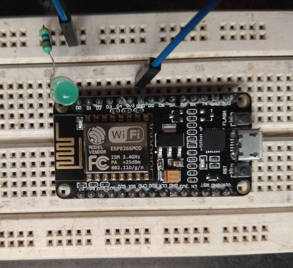
Practical Implementation of Circuit
Working Procedure
This project is designed to control an LED using ESP8266, which is programmed as a web server. We need the IP address of the device to access html content which we are programming.
- Edit the above code in Arduino IDE, replace WiFi Name and Password with yours
- Save
- Compile
- Upload
- Open Serial Monitor at a baud rate of 115200.
- Press the reset button which is provided on ESP8266, then this module displays the IP address of the ESP8266.
- Copy that IP address which is displaying on Serial Monitor and paste it on browser of our system (which is connected to the same WiFi network).
- Click on ON and OFF button to send ON or OFF command to ESP8266.
Then LED which is connected at D0 pin of ESP8266 will be controlled based on the given command.
How to control through Internet ?
We are not going to explain this in detail in this tutorial. Most of the wifi routers available in the market supports DDNS (Dynamic DNS) and port forwarding. This can be used to access the web page served by ESP8266. In real IoT applications we need to connect ESP8266 to a internet server. We will explain those in next tutorials.
Comments